Turn physical parts into accurate digital models
Turn physical parts into accurate digital models
Turn physical parts into accurate digital models
On-site 3D scanning, reverse engineering, and dimensional inspection for the parts, assets, and systems your operation depends on.
On-site 3D scanning, reverse engineering, and dimensional inspection for the parts, assets, and systems your operation depends on.
On-site 3D scanning, reverse engineering, and dimensional inspection for the parts, assets, and systems your operation depends on.

Based in Greater Vancouver & Greater Victoria, BC
Based in Greater Vancouver & Greater Victoria, BC
Based in Greater Vancouver & Greater Victoria, BC
A-DATUM provides 3D scanning, reverse engineering, CAD modeling, dimensional inspection, GD&T, and engineering drawing services. With over 20 years of combined engineering and manufacturing experience, we help turn existing parts and assemblies into accurate CAD models and engineering drawings.
From scanning and dimensional inspection to CAD reconstruction and GD&T, our goal is simple: turn physical parts into useful engineering data for manufacturing, inspection, modification, or reproduction.
0.02 mm
0.02 mm
0.02 mm
Resolution Up to
Resolution Up to
0.02 mm
0.02 mm
0.02 mm
Accuracy Up to
Accuracy Up to
0.015 + 0.035 mm
0.015 + 0.035 mm
0.015 + 0.035 mm
Volumetric Accuracy
Volumetric Accuracy
Engineering Workflow
Engineering Workflow

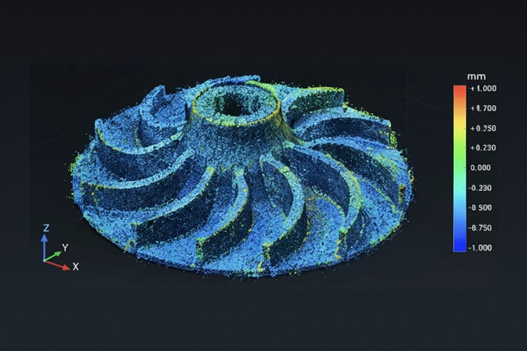
3D Scanning & Data Capture

High-Accuracy Scanning:
Parts, assemblies, tooling, and large-scale systems.
Versatile Surface Capture:
Various sizes, materials, colors, and surface finishes.
Clean Mesh Generation:
Optimized scan data ready for CAD reconstruction and analysis.
3D-Ready Outputs:
STL, OBJ, PLY and other formats for 3D printing and engineering applications.
3D Scanning & Data Capture
High-Accuracy Scanning:
Parts, assemblies, tooling, and large-scale systems.
Versatile Surface Capture:
Various sizes, materials, colors, and surface finishes.
Clean Mesh Generation:
Optimized scan data ready for CAD reconstruction and analysis.
3D-Ready Outputs:
STL, OBJ, PLY and other formats for 3D printing and engineering applications.
3D Scanning & Data Capture
High-Accuracy Scanning:
Parts, assemblies, tooling, and large-scale systems.
Versatile Surface Capture:
Various sizes, materials, colors, and surface finishes.
Clean Mesh Generation:
Optimized scan data ready for CAD reconstruction and analysis.
3D-Ready Outputs:
STL, OBJ, PLY and other formats for 3D printing and engineering applications.

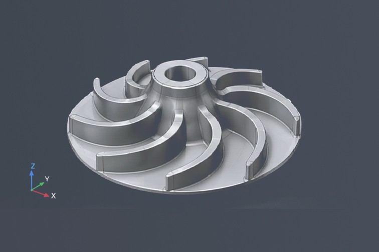
Reverse Engineering & CAD Modeling
Scan-to-CAD:
Accurate reconstruction of physical components into engineering CAD.
Surface & Solid Modeling:
Professional modeling using CATIA, Geomagic Design X, and SOLIDWORKS.
Design Intent Recovery:
Reconstruct nominal geometry, features, interfaces, and functional relationships.
CAD Deliverables:
STEP, IGES, Parasolid, CATPart, SLDPRT and other industry-standard formats.
Reverse Engineering & CAD Modeling
Scan-to-CAD:
Accurate reconstruction of physical components into engineering CAD.
Surface & Solid Modeling:
Professional modeling using CATIA, Geomagic Design X, and SOLIDWORKS.
Design Intent Recovery:
Reconstruct nominal geometry, features, interfaces, and functional relationships.
CAD Deliverables:
STEP, IGES, Parasolid, CATPart, SLDPRT and other industry-standard formats.
Reverse Engineering & CAD Modeling
Scan-to-CAD:
Accurate reconstruction of physical components into engineering CAD.
Surface & Solid Modeling:
Professional modeling using CATIA, Geomagic Design X, and SOLIDWORKS.
Design Intent Recovery:
Reconstruct nominal geometry, features, interfaces, and functional relationships.
CAD Deliverables:
STEP, IGES, Parasolid, CATPart, SLDPRT and other industry-standard formats.


Inspection & Dimensional Analysis
Inspection & Dimensional Analysis Scan-to-CAD Comparison:
Validate reconstructed CAD against original scan data.
Manufacturing Inspection:
Compare manufactured parts against original CAD to verify dimensional accuracy.
Assembly & Line Verification:
Check alignment, positioning, interfaces, and clearances of tooling and assembly systems.
Inspection Reporting:
3D deviation maps, dimensional results, sections, and engineering reports.
Inspection & Dimensional Analysis
Inspection & Dimensional Analysis Scan-to-CAD Comparison:
Validate reconstructed CAD against original scan data.
Manufacturing Inspection:
Compare manufactured parts against original CAD to verify dimensional accuracy.
Assembly & Line Verification:
Check alignment, positioning, interfaces, and clearances of tooling and assembly systems.
Inspection Reporting:
3D deviation maps, dimensional results, sections, and engineering reports.
Inspection & Dimensional Analysis
Inspection & Dimensional Analysis Scan-to-CAD Comparison:
Validate reconstructed CAD against original scan data.
Manufacturing Inspection:
Compare manufactured parts against original CAD to verify dimensional accuracy.
Assembly & Line Verification:
Check alignment, positioning, interfaces, and clearances of tooling and assembly systems.
Inspection Reporting:
3D deviation maps, dimensional results, sections, and engineering reports.

Engineering Drawings & GD&T
Production Drawings:
Manufacturing-ready 2D drawings and shop-floor documentation.
GD&T Definition:
Functional datums and geometric tolerances based on design requirements.
Manufacturing-Based Tolerancing:
Tolerances selected with process capability and inspection in mind.
Cost-Effective Definition:
Balance functionality, manufacturability, quality, and production cost.
Engineering Drawings & GD&T
Production Drawings:
Manufacturing-ready 2D drawings and shop-floor documentation.
GD&T Definition:
Functional datums and geometric tolerances based on design requirements.
Manufacturing-Based Tolerancing:
Tolerances selected with process capability and inspection in mind.
Cost-Effective Definition:
Balance functionality, manufacturability, quality, and production cost.
Engineering Drawings & GD&T
Production Drawings:
Manufacturing-ready 2D drawings and shop-floor documentation.
GD&T Definition:
Functional datums and geometric tolerances based on design requirements.
Manufacturing-Based Tolerancing:
Tolerances selected with process capability and inspection in mind.
Cost-Effective Definition:
Balance functionality, manufacturability, quality, and production cost.
Data You Can Design and Decide With

Capture complex geometry with precision
We digitally measure physical parts and assemblies, creating accurate point-cloud and mesh data for reverse engineering and inspection.
Production-ready CAD from existing parts
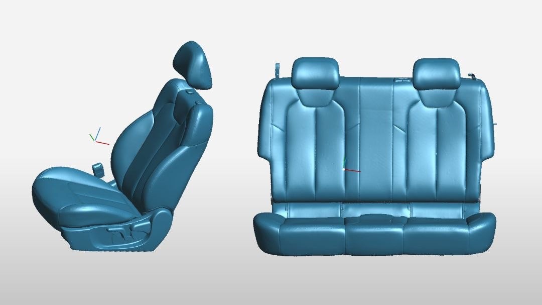
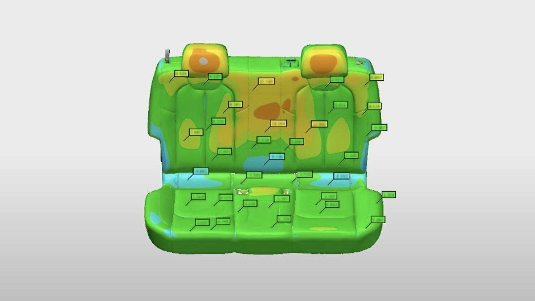
Engineering data your team can use
Receive validated CAD models, deviation analysis, inspection reports, and 2D drawings with GD&T—ready to support manufacturing, quality, and part reproduction.

Data You Can Design and Decide With
Capture complex geometry with precision
We digitally measure physical parts and assemblies, creating accurate point-cloud and mesh data for reverse engineering and inspection.
Production-ready CAD from existing parts
Engineering data your team can use
Receive validated CAD models, deviation analysis, inspection reports, and 2D drawings with GD&T—ready to support manufacturing, quality, and part reproduction.
Data You Can Design and Decide With
Capture complex geometry with precision
We digitally measure physical parts and assemblies, creating accurate point-cloud and mesh data for reverse engineering and inspection.
Production-ready CAD from existing parts
Engineering data your team can use
Receive validated CAD models, deviation analysis, inspection reports, and 2D drawings with GD&T—ready to support manufacturing, quality, and part reproduction.
Portfolio Examples
These examples represent projects across the automotive, power-generation, and pump industries. Our scope extends beyond 3D scanning to accurate CAD reconstruction and complete engineering drawings containing the dimensions, assembly interfaces, tolerances, notes, and GD&T required for manufacturing, inspection, and assembly.

Axle Assembly Geometry Capture
Full-component 3D scanning of a large axle assembly to capture mounting features, interfaces, and overall geometry.

Precision 3D Scanning for Complex Assemblies
Transforming complex mechanical components into accurate digital models for reverse engineering and product development.

Open Impeller Geometry Capture
3D scanning of complex impeller geometry for reverse engineering, CAD reconstruction, dimentional inspection, and part reproduction.

Reverse Engineering of a Closed Impeller
3D scanning of a cast closed impeller to capture its airfoil geometry and generate accurate data for CAD reconstruction, dimentional inspection, and engineering documentation.
Portfolio Examples
These examples represent projects across the automotive, power-generation, and pump industries. Our scope extends beyond 3D scanning to accurate CAD reconstruction and complete engineering drawings containing the dimensions, assembly interfaces, tolerances, notes, and GD&T required for manufacturing, inspection, and assembly.
Axle Assembly Geometry Capture
Full-component 3D scanning of a large axle assembly to capture mounting features, interfaces, and overall geometry.
Precision 3D Scanning for Complex Assemblies
Transforming complex mechanical components into accurate digital models for reverse engineering and product development.
Open Impeller Geometry Capture
3D scanning of complex impeller geometry for reverse engineering, CAD reconstruction, dimentional inspection, and part reproduction.
Reverse Engineering of a Closed Impeller
Mating faces and hole patterns captured for accurate 3D modeling and inspection.
Axle Housing
Axle geometry captured to rebuild accurate CAD models and define key interfaces.
Turbomachinery Component
Impeller
Mechanical Interface Component
Portfolio Examples
These examples represent projects across the automotive, power-generation, and pump industries. Our scope extends beyond 3D scanning to accurate CAD reconstruction and complete engineering drawings containing the dimensions, assembly interfaces, tolerances, notes, and GD&T required for manufacturing, inspection, and assembly.
Bring us the challenge, we'll map the next step
Share a few photos, an existing drawing, or a quick description of the part. We’ll help determine the right capture and delivery approach.
Bring us the challenge, we'll map the next step
Share a few photos, an existing drawing, or a quick description of the part. We’ll help determine the right capture and delivery approach.
Bring us the challenge, we'll map the next step
Share a few photos, an existing drawing, or a quick description of the part. We’ll help determine the right capture and delivery approach.
A-Datum transforms physical components into accurate CAD models, inspection data, and engineering documentation.
Location
Victoria, British Colombia
Canada-wide Project Support
A-DATUM
Copyright © 2026 – All Right Reserved
A-Datum transforms physical components into accurate CAD models, inspection data, and engineering documentation.
Location
Victoria, British Colombia
Canada-wide Project Support
A-DATUM
Copyright © 2026 – All Right Reserved
A-Datum transforms physical components into accurate CAD models, inspection data, and engineering documentation.
Location
Victoria, British Colombia
Canada-wide Project Support
A-DATUM
Copyright © 2026 – All Right Reserved